※ IEPE(ICP) 타입 센서의 전원 공급 장치인 IEPE(ICP) Power Supply는 IEPE(Integrated Electronics Piezo-Electric) 타입 또는 ICP 타입의 센서, 가속도센서(Accelerometer), 마이크로폰(Microphone),힘 센서(Force Sensor), 압력센서(Pressure Sensor)등을 작동시키기 위해 필요한 전원을 공급해 주는 전원 공급장치를 말합니다
*일반 직류 전원 장치와 작동 방식이 다릅니다
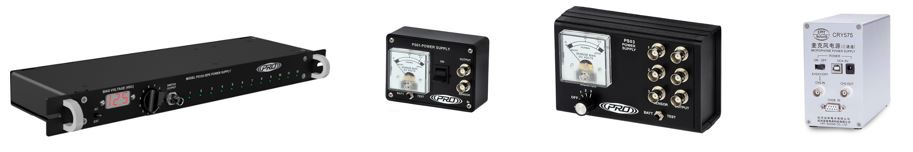
12채널, 220V 전원 사용 1채널, 배터리 타입 3채널, 배터리 타입 3채널,5VDC 전원 사용
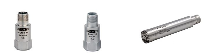
가속도센서 (IEPE 타입) 속도 센서(IEPE 타입) 마이크로폰(IEPE 타입)
대부분의 진동/소음 전용 온라인 모니터링 장비 또는 휴대용 분석장비들은
내부에 IEPE 전원을 공급할 수 있는 회로가 장착되어 있습니다
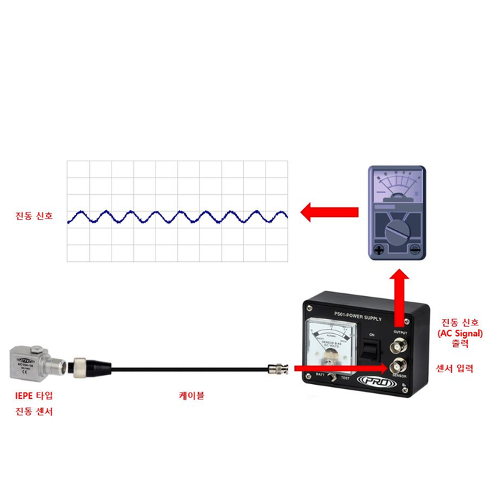
만약 이 기능을 지원하지 않는다면 별도의 IEPE Power Supply에 연결하여
AC 신호(진동)를 출력 받아서 측정 장비에 연결하여 분석 또는 측정 하여야 합니다
※ IEPE전원의 내부 회로는 아래와 같습니다
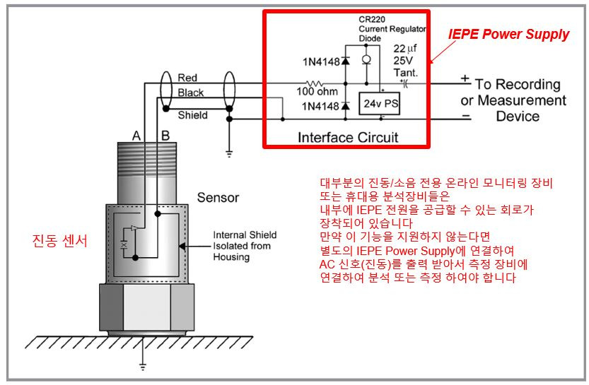
IEPE Power Supply Circuit
▶참고 사항
CTC 진동 센서 공급 전원은 전압 18-30VDC, 전류: 2-10mA를 필요로 하며 보통 24VDC(2mA)를 추천합니다
100ohm, ¼ wat resistor와 1N4148 다이오드는 electrostatic discharge(정전 방전)을 막기 위해 사용되며
2-4mA constant current regulator diode는 센서에 필요한 Bias current를 공급합니다
또한 22uf tantalum capacitor는 시그널에서 DC 성분을 제거합니다.
회로 안의 모든 부품들은 극성(Polarity)를 가지고 있으며 제대로 작동하기 위해 반드시 바르게 연결되어야 합니다
CTC 진동 센서는 모두 내부 쉴드를 가지고 있고 이 쉴드는 마이너스 터미널에 연결되어야 합니다
또한 진동 센서의 외함은 노이즈 제거를 위해 회로로 부터 절연되었습니다.
각각의 센서는 명시된 바이어스 전압을 타고 신호를 전송하는데 이것은 보통 12V 바이어스 전압을 타고 +/- 5V의 형태로 발생 됩니다
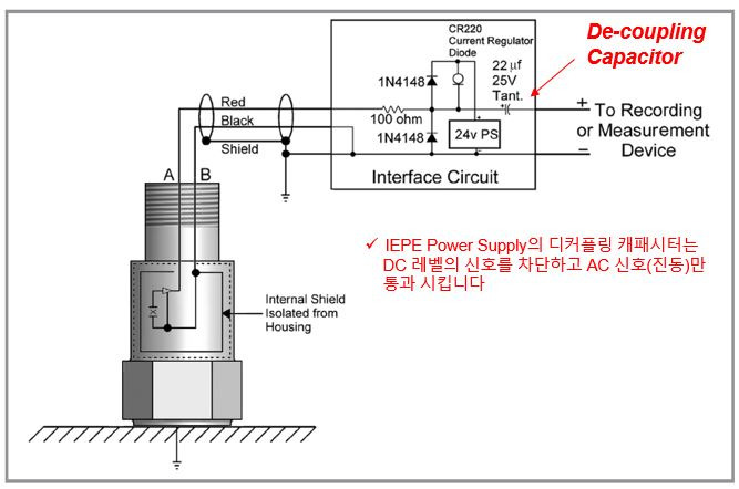
※ 즉, DC신호는 제거하고 AC(진동)신호만 통과 시킵니다
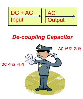
※ 아래와 같이 AC신호만을 취득 할 수 있습니다
※ AC(진동)신호 vs 바이어스 전압(Bias Voltage)와의 관계
▶바이어스 전압(DC Voltage)은 외부의 진동의 없을 때 일반적으로 12~14V 사이입니다
▶진동 센서의 출력 신호 전압은 바이어스 전압 근처에서 발생되기 때문에 Negative(마이너스)가 될 수 없습니다▶Capacitor CC는 제공된 Zero-Based AC Signal를 제공하는 장비로 부터 Bias Voltage를 제거 합니다
▶전압 신호의 최대값은 공급되는 전류에 의해 결정 됩니다
(공급되는 전류의 일반적인 전압 값은 18~30VDC 범위임)
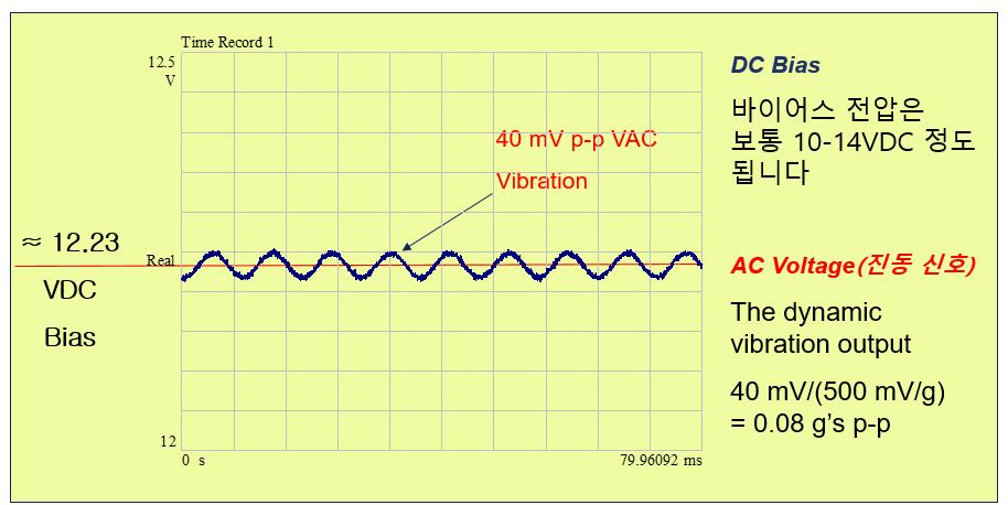
AC(진동)신호 vs 바이어스 전압(Bias Voltage)
바이어스 이어스 전압(Bias Voltage) 확인 방법
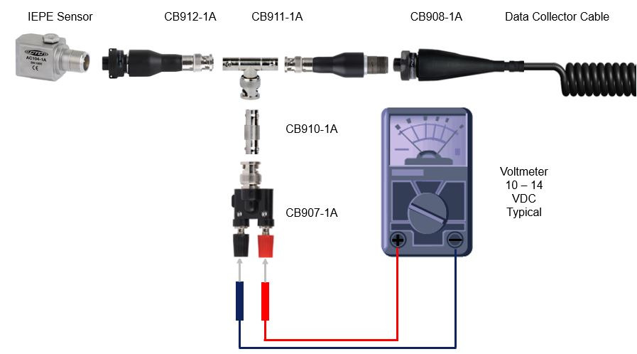
바이어스 이어스 전압(Bias Voltage) 확인 방법(터미널)
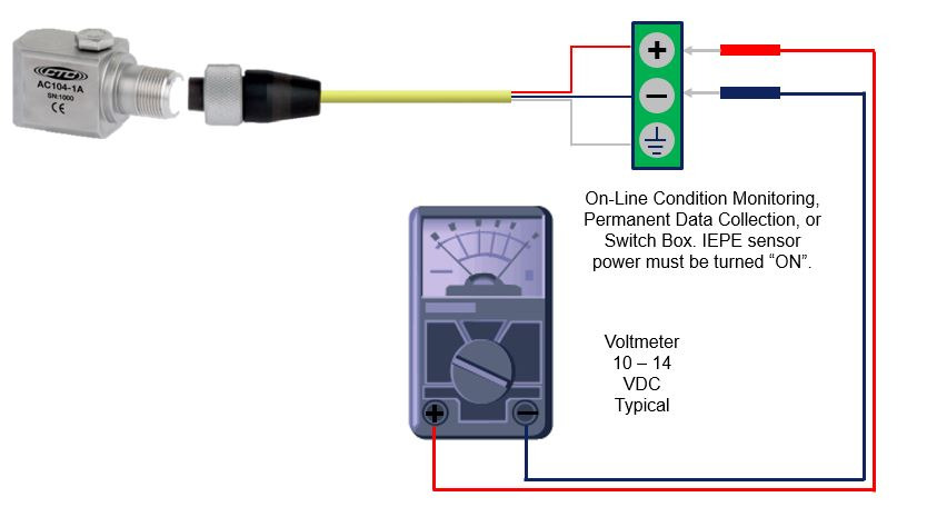
▶대부분의 IEPE 타입 센서의 바이어스 전압 범위는 10 – 14 VDC 입니다
▶만일 16 VDC 이상의 전압값이 출력되면 센서, 케이블, 커넥터가 연결이 안되어 있을 수 있습니다
▶만일 4 VDC 이하의 전압값이 출력되면 센서, 케이블, 커넥터가 Short Circuit, 즉 단락/합선 된 상태입니다
▶IEPE 타입의 바이어스 전압 범위는 제조사 마다 조금씩 틀릴 수 있습니다
아래 내용은 위키피디아에 설명된 IEPE Power Supply에 대한 내용이니 한번 참고해보시기 바랍니다
The abbreviation IEPE stands for Integrated Electronics Piezo-Electric. It characterises a technical standard for piezoelectric sensors which contain built-in impedance conversion electronics. IEPE sensors are used to measure acceleration, force or pressure. Measurement microphones also apply the IEPE standard. Other proprietary names for the same principle are ICP, CCLD, IsoTron or DeltaTron.
The electronics of the IEPE sensor (typically implemented as FET circuit) converts the high impedance signal of the piezoelectric material into a voltage signal with a low impedance of typically 100 Ω. A low impedance signal is advantageous because it can be transmitted across long cable lengths without a loss of signal quality. In addition, special low noise cables, which are otherwise required for use with piezoelectric sensors, are no longer necessary.
The sensor circuit is supplied with constant current. A distinguishing feature of the IEPE principle is that the power supply and the sensor signal are transmitted via one shielded wire.
Most IEPE sensors work at a constant current between 2 and 20 mA. A common value is 4 mA. The higher the constant current the longer the possible cable length. Cables of several hundred meters length can be used without a loss of signal quality. Supplying the IEPE sensor with constant current, results in a positive bias voltage, typically between 8 and 12 volts, at the output. The actual measuring signal of the sensor is added to this bias voltage.[1][2][3] The supply or compliance voltage of the constant current source should be 24 to 30 V which is about two times the bias voltage. This ensures maximum amplitudes in positive and negative direction.
A typical IEPE sensor supply with 4 mA constant current and 25 V compliance voltage has a power consumption of 100 mW. This can be a drawback in battery powered systems. For such applications low-power IEPE sensors exist which can be operated at only 0.1 mA constant current from a 12 V supply. This may save up to 90 % power. Bias voltage and output voltage swing of an IEPE sensor
Many measuring instruments designed for piezoelectric sensors or measurement microphones have an IEPE constant current source integrated at the input. In measuring instruments with IEPE input the bias voltage is often used for sensor detection. If the signal lies close to the constant current supply voltage, there is no sensor present or the cable path has been interrupted. A signal close to the saturation voltage, indicates a short-circuit in the sensor or cable. In between these two limits a functional sensor has been detected. The bias voltage is cut off by a coupling capacitor at the instrument input and only the AC signal is processed further. IEPE sensor connected to the input of an instrument
Piezoelectric sensors which do not possess IEPE electronics, meaning with charge output, remain reserved for applications where lowest frequencies, high operating temperatures, an extremely large dynamic range, very energy saving operation or extremely small design is required.
출처: 위키피디아
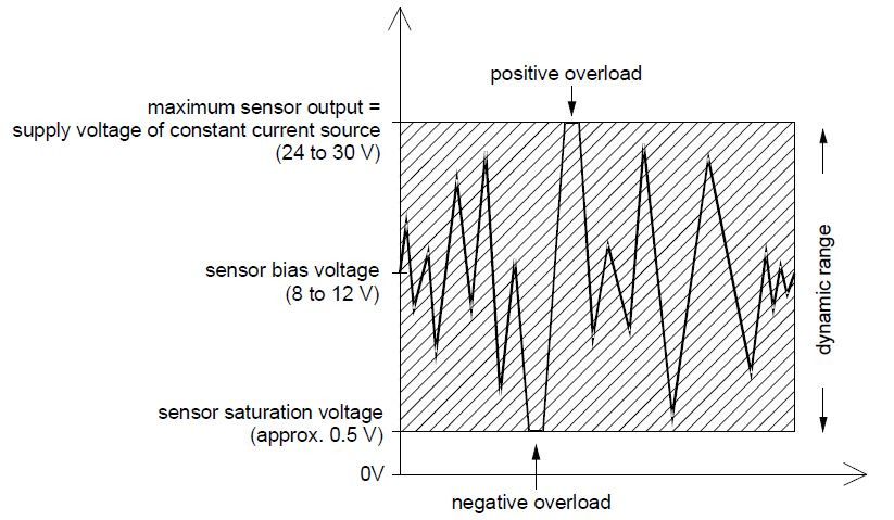
Dynamic range of IEPE transducers
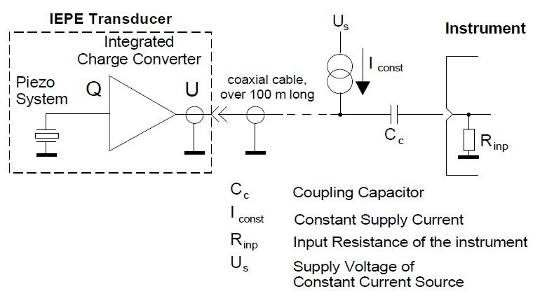
IEPE principle
'기술자료실' 카테고리의 다른 글
| 진동센서, 비접촉 변위센서 Proximity Probe 비교 자료 (0) | 2025.04.21 |
|---|---|
| IEPE/ICP 타입의 진동 센서를 이용한 초음파 진동 측정 기술 (0) | 2025.04.18 |
| SC300 시리즈 진동 시그널 컨디셔너 (0) | 2025.04.18 |
| 해상풍력발전기의 진동 측정 (0) | 2025.04.18 |
| 진동 가속도센서의 센싱 방식(Shear vs Compression) (0) | 2025.04.18 |


댓글